Robot Marker
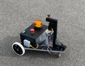
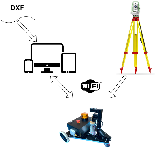
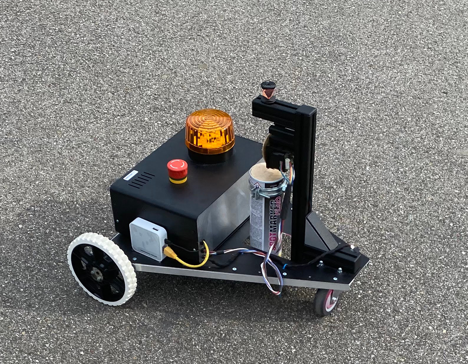
Robot for automatic positioning of magnets for coordinate network.
- Autonomous operation
- Web-based user interface
- Platform support – Win, iOS, Android
- Time saving compared to manual use
- Marking accuracy of 2 mm
- Lower weight
- Ready to use in 2 minutes
- Easy to use
Work packages
The development of a robot is a complex process that involves a variety of disciplines and areas of expertise. Here is a detailed description of the various steps performed in the development of the marking robot, including concept definition, implementation of control in the Robot Operating System (ROS2), definition and implementation of communication with a geodetic total station, development of the user interface and complete system development (software, mechanical hardware, electrical hardware):
1. concept definition
Requirements analysis:
- Identify the specific requirements and objectives of the robot.
- Definition of the operating environment and the tasks to be solved.
- Definition of functional and non-functional requirements.
Feasibility study:
- Technological feasibility: Investigation of available technologies and components.
- Economic feasibility: cost analysis and budget planning.
- Time feasibility: Creation of a schedule and milestones.
System architecture:
- Rough draft of the system architecture, including hardware and software components.
- Definition of the communication interfaces and interactions between the components.
2. implementation of the controller in the Robot Operating System (ROS2)
Setting up the development environment:
- Installation and configuration of the ROS2 development environment.
- Selection of suitable ROS2 distributions based on the project requirements.
Modeling of the robot:
- Creation of a URDF (Unified Robot Description Format) model to describe the physical structure of the robot.
- Simulation of the robot in Gazebo.
Development of the control algorithms:
- Implementation of basic control for drives and sensors.
- Use of ROS2 nodes for modular structuring of the control software.
- Implementation of the path planning algorithms.
Test and validation:
- Execution of tests in the simulation environment and in real operation.
- Verification of the control algorithms and adjustments based on the test results.
3. definition and implementation of communication with the geodetic total station
Interface definition:
- Analysis of the communication protocols of the geodetic total station.
- Definition of the communication protocol
Implementation of the communication interface:
- Development of ROS2 nodes for communication with the total station.
- Processing of the received data and integration into the robot’s control algorithms.
Calibration and synchronization:
- Calibration of the total station and the robot to ensure precise position data.
- Synchronization of time stamps to ensure data integrity.
Test and validation:
- Test of the communication interface in the real environment.
- Verification of the accuracy and reliability of the position data.
4. development of the user interface
Requirements analysis:
- Definition of user requirements and expectations.
- Determining the functions and design of the user interface.
Prototyping:
- Creating mockups and wireframes of the user interface.
- Conducting user studies and obtaining feedback.
Implementation:
- Development of the user interface using JScript and Angular technologies
- Integration of the user interface with the ROS2 control software.
Testing and validation:
- Conducting usability tests with end users.
- Customization based on user feedback.
5. complete system development (software, mechanical hardware, electrical hardware)
Mechanical hardware development:
- Detailed design and construction of the mechanical components of the robot.
- Manufacturing and assembly of the mechanical parts.
- Performance of load tests and adjustments.
Electrical hardware development:
- Designing the electronic circuit diagrams and PCB layouts.
- Production and assembly of the circuit boards.
- Integration of sensors, actuators and control units.
Software development:
- Integration of all software modules (control algorithms, communication interfaces, user interface).
- Carrying out extensive tests and debugging.
- Optimization of the software in terms of performance and reliability.
System integration:
- Assembling all components (mechanical, electrical and software).
- Carrying out system tests to check overall functionality.
- Calibration and fine-tuning of the entire system.
Validation and verification:
- Carrying out extensive tests in the target environment.
- Ensuring that all requirements are met and that the robot functions reliably.
Documentation and handover:
- Preparation of technical documentation and user manuals.
- Training of end users and handover of the system to the customer.
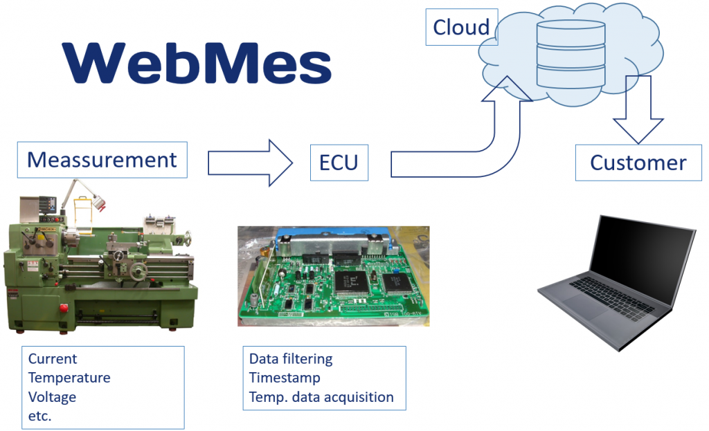
WebMes
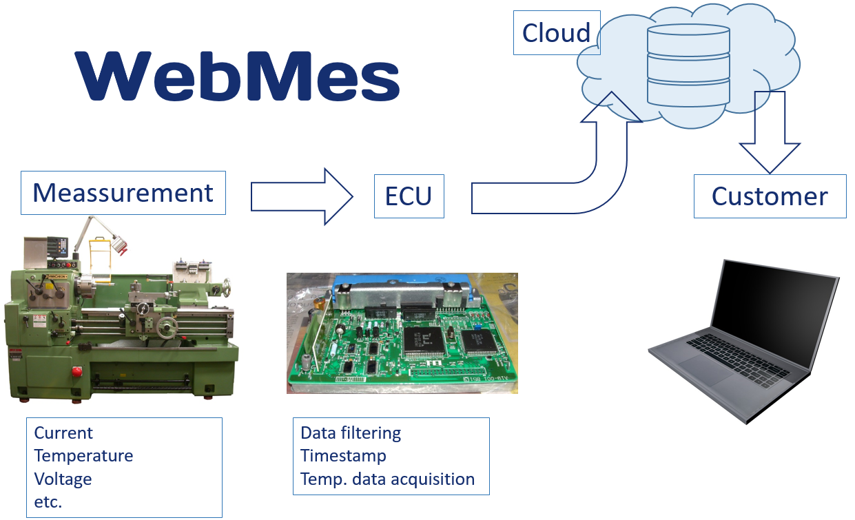
System for contactless load measurement of industrial machines in real time.
- Data transfer using wireless technology
- Storage of the measured data in the cloud database
- Presentation of the measured data
- Data export in various formats (Excel, PDF, png, CSV …)
- Productivity increase of the device
- Better scheduling
- Manufacturing cost overview
- Optimizing technological breaks
Work packages
- Design and development of the HW and SW architecture
- Definition of the communication interface between HW and SW
- Programming the control / measuring device in C
- Programming of the user interface and the interface to the database in Java
- Measured data was saved and edited in the MySQL database
Remote Desktop (Concept)
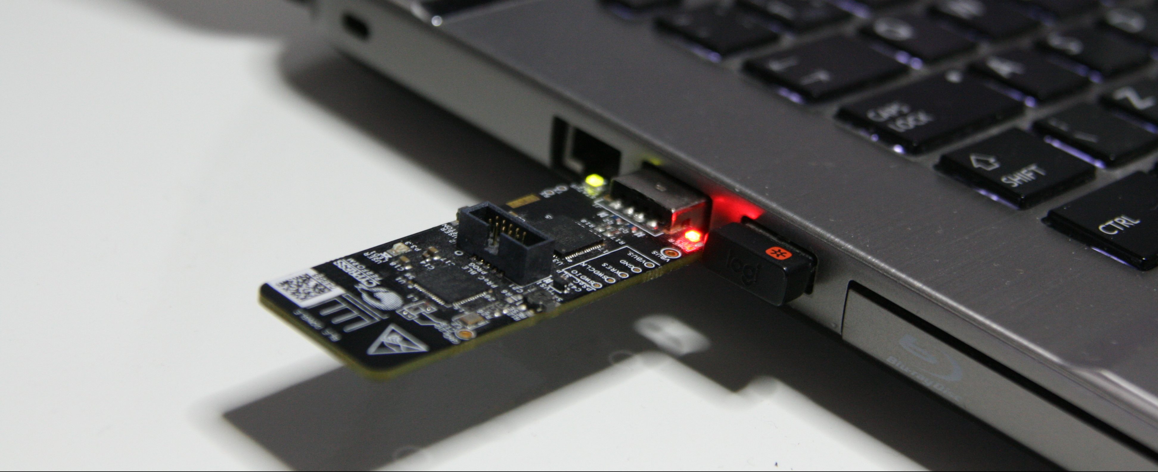
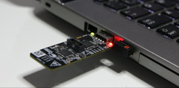
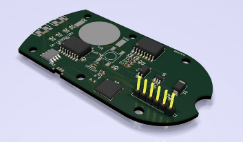
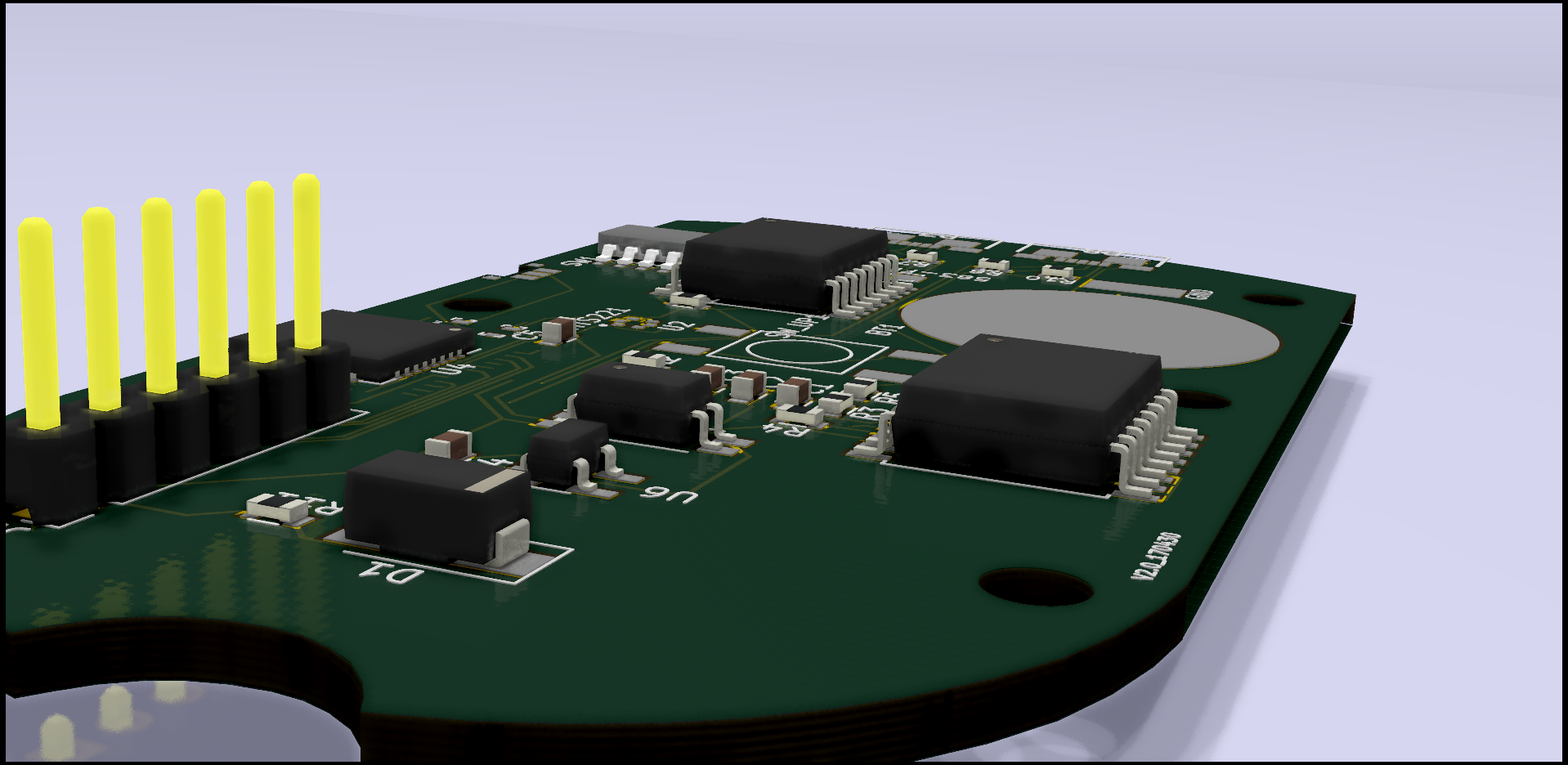
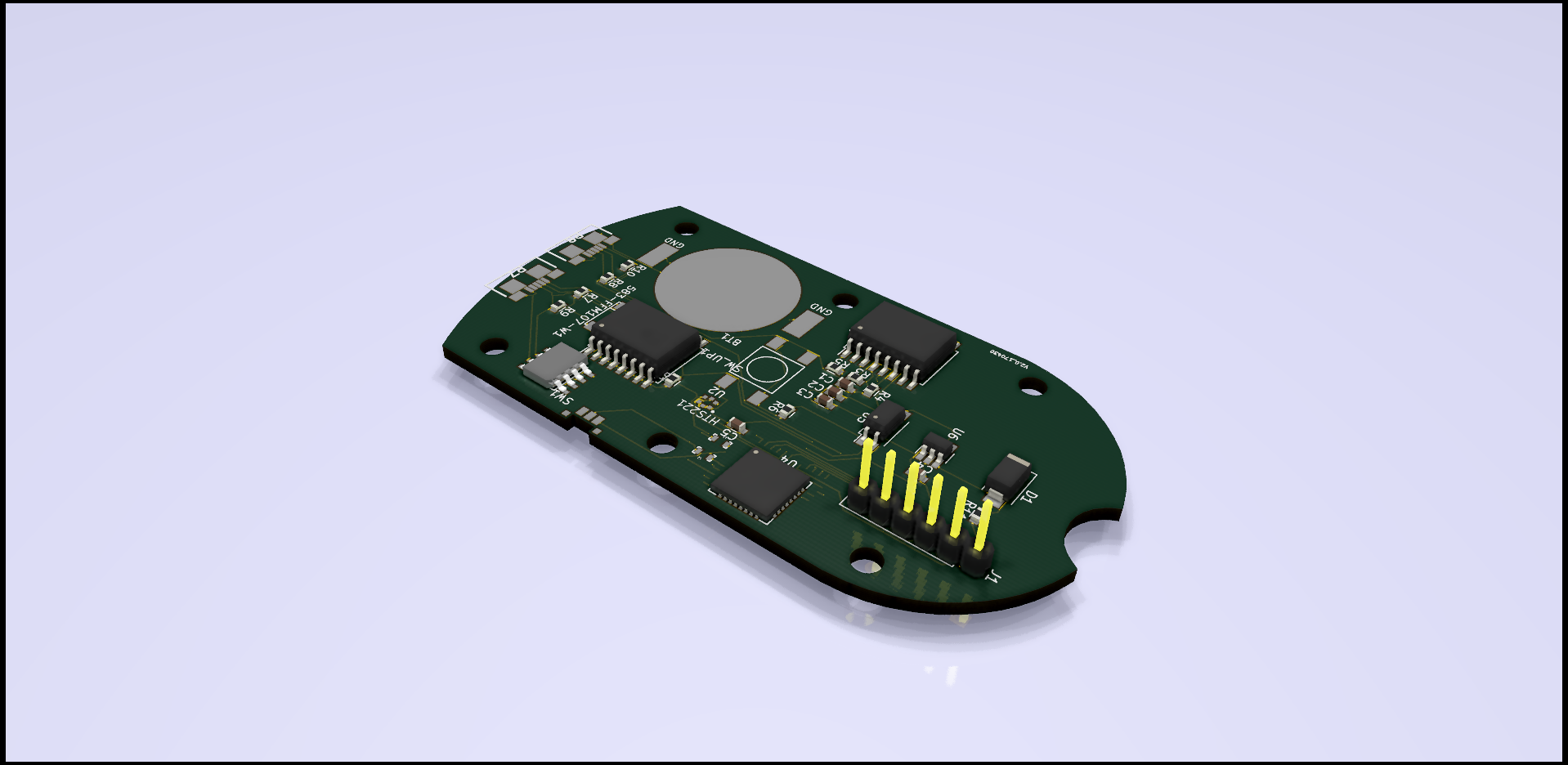
Universal data logger with Bluetooth
- Implicit measurement of temperature and relative humidity
- Possibility of adding sensors – pressure, gas sensor, temperature…. according to customer requirements
- Communication via Bluetooth Low Energy
- Measuring period 2 seconds – 1 day
- Minimal power consumption
- Possibility of connecting an external power supply
- Compact dimensions
Work packages
- Architecture server – client
- C – Programming the firmware of the Cypress Bluetooth chip (server)
- Cypress PSoC (programmable system-on-chip) was used as the control unit – all necessary interfaces are already integrated in the chip and can also be configured – lower development costs and greater flexibility in the event of changes
- Programming the client in Java
- Complete hardware development and prototype production
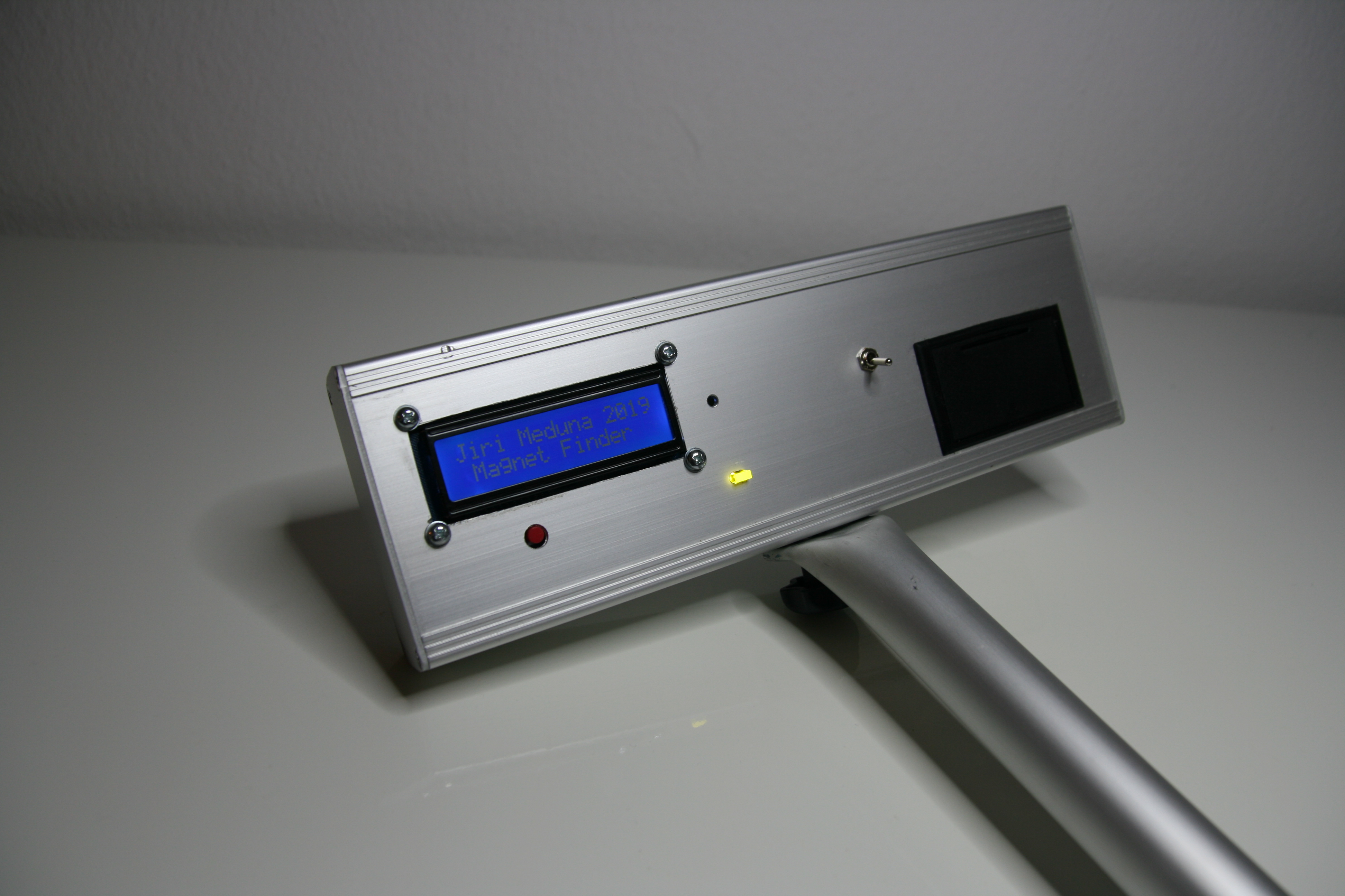
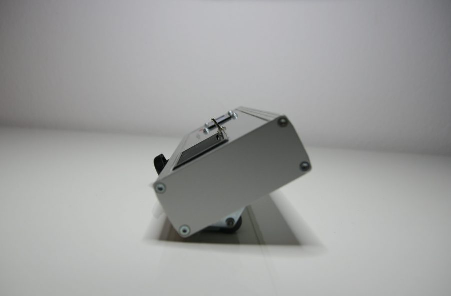
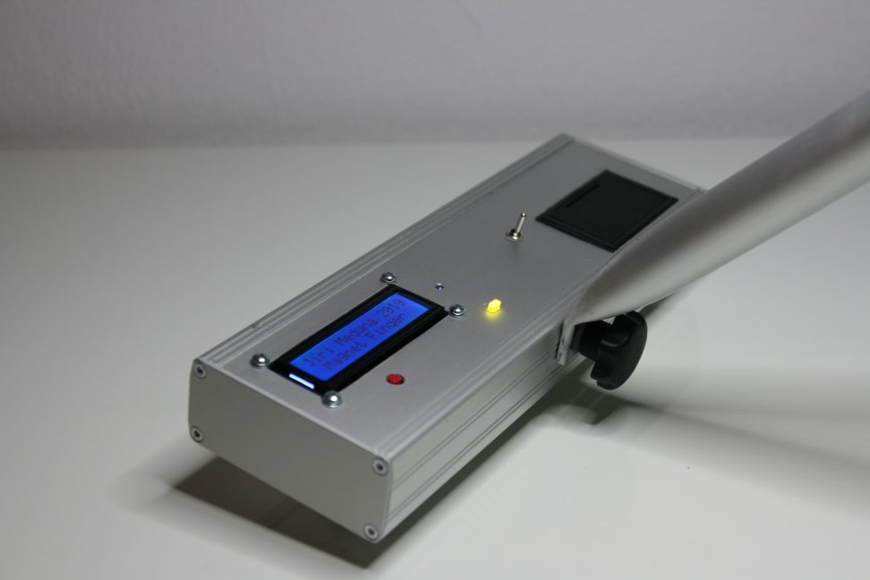
Magnet Finder
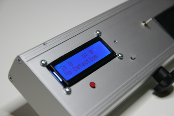
Device for the correct determination of the polarity of a magnet in the network of the coordinate system
- Acoustic and visual signaling when a magnet is defected
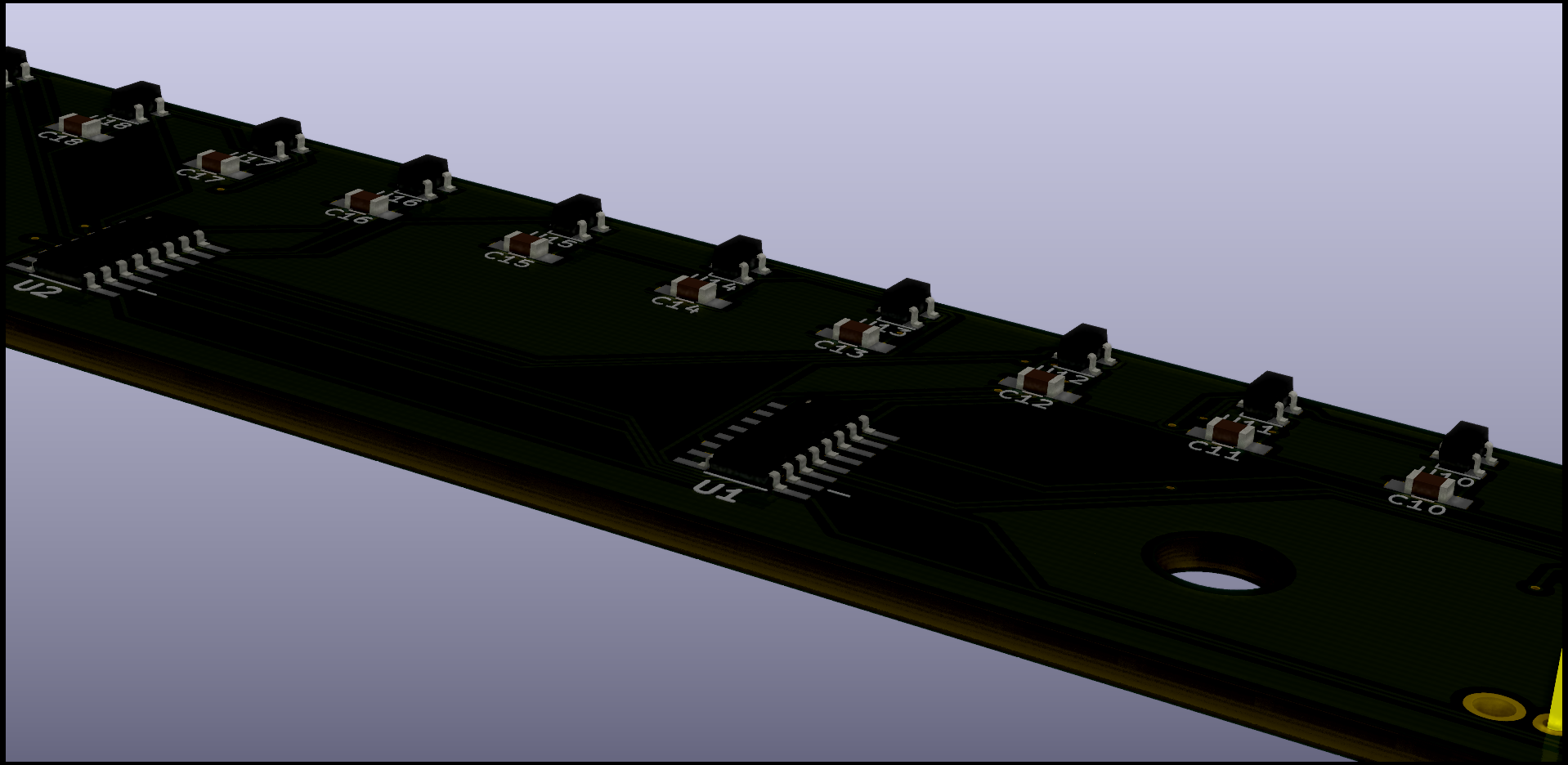
- Advanced algorithm for determining the position of the magnet
- Indication of the area and the intensity of the magnet on a display
- Easy handling
- Productivity increase when installing magnets
- Minimize potential errors
Work packages
- Processor ATmega328 was used as the control unit
- C – Programming of the firmware
- Design and development of the electronics and sensors
- Complete manufacture of mechanical parts

